


 Eng
Eng 
 中文简体
中文简体

What are the four types of metal stamping?
 2026.08.13
 Industry News
Metal stamping is a foundational manufacturing category in modern industrial production. It converts flat metallic sheets or continuous coiled metal strips into precisely engineered three dimensional components through controlled mechanical deformation. When manufacturing facilities produce Stamping Metal Parts, they rely on specialized press machinery, hardened steel or carbide tooling dies, and precise force applications to shear, bend, coin, and draw raw materials. Understanding the core structural variations within this field allows engineers, production managers, and component designers to choose the optimal manufacturing method for specific project requirements.
The industrial sheet metal forming sector centers on four primary manufacturing methodologies: progressive die stamping, deep draw stamping, transfer die stamping, and four slide stamping. Each method offers distinct operational mechanics, production speeds, tooling architecture, and geometric capabilities. Selecting the right process impacts component unit costs, scrap material generation, dimensional accuracy, and long term production throughput.
Industrial Overview of Metal Stamping Operations
Sheet metal conversion relies on plastic deformation principles where applied stress exceeds the yield point of the material without surpassing its ultimate tensile strength. Cold forming presses deliver thousands of kilonewtons of force into structured die sets to shape metal stock at ambient temperatures. This process yields durable components with consistent grain structures and repeatable dimensions.
The global manufacturing landscape depends on Stamping Metal Parts across sectors such as automotive assembly, aerospace systems, consumer electronics, medical device fabrication, renewable energy equipment, and industrial hardware. Raw materials enter stamping systems in several formats, including continuous coils, cut strips, or pre punched individual blanks. Material thickness spans light gauge foils below one millimeter up to heavy structural plate stock exceeding six millimeters.
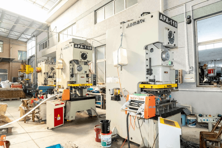
Press machinery classified by drive mechanics includes mechanical crank presses, hydraulic presses, and servo motor presses. Mechanical presses yield high operational cycle speeds ideal for volume production. Hydraulic presses deliver constant tonnage throughout the entire stroke length, making them suitable for deep stretching actions. Servo presses grant precise programmable control over punch speed and position during the stroke cycle, allowing fabricators to optimize material flow for complex structural shapes.
Core Engineering Principles for Stamping Metal Parts
Successful sheet metal shaping depends on understanding material behavior, tooling mechanics, and fluid friction management during forming operations.
Plastic Deformation and Material Grain Flow
When a punch contacts raw metal stock, internal shear and tensile forces induce atomic slip along crystallographic planes. Material deformation begins with elastic flex before transitioning into permanent plastic deformation. Managing grain orientation relative to major bend axes prevents micro cracking along outer bend radiuses. Aligning primary bending lines perpendicular to the rolling direction of sheet metal coils improves structural integrity and fatigue endurance.
Tooling Die Design and Punch Mechanics
A stamping die set comprises a upper shoe attached to the press ram and a lower shoe mounted on the press bolster bed. Guide posts maintain alignment between upper punch components and lower die cavities within precise tolerances, often measured in micrometers. Die plates crafted from air hardened tool steels or tungsten carbide resist severe abrasive and adhesive wear across millions of stroke cycles. Clearances between shearing punch edges and die cavity walls are calculated based on material hardness and thickness to produce clean sheared edges with minimal burr height.
Tribology and Friction Management
High contact pressure generates substantial frictional heat at the interface between tool steel dies and raw metallic surfaces. Specialized metalworking fluids mitigate friction, cool tooling components, and prevent material galling or metal pickup. Water soluble synthetic fluids perform effectively during high speed shallow forming operations, whereas heavy duty oil based lubricants with extreme pressure additives manage the severe friction generated during heavy gauge drawing operations.
Progressive Die Stamping
Progressive die stamping represents a high speed, automated manufacturing approach designed for mass producing small to medium sized components from continuous metal coils.
Structural Configuration and Feeding Sequence
In progressive die stamping, a continuous metal coil unwinds from a motorized uncoiler, passes through a straightening unit, and enters an automated feeder. The press feeds the metal strip into the die set by a fixed pitch length with every stroke. The raw material remains connected to a continuous carrier strip as it moves sequentially through multiple adjacent workstation cavities inside a single unified die block.
Initial stations within a progressive die set perform primary piercing and notched cutout operations to establish internal hole features and define the outer part outline. Pilot pins enter pre pierced reference holes in subsequent stations to ensure precise strip positioning before upper punches descend. Intermediate stations execute secondary forming operations, such as bending, embossing, coining, and lancing. The final station cuts the finished part away from the carrier strip, allowing completed components to exit through discharge chutes.
Key Operational Advantages for High Volume Production
Progressive die stamping yields extraordinary processing efficiency. Presses operate at speeds ranging from dozens to hundreds of strokes per minute, depending on part geometry and press tonnage capacity. Because multiple operations occur simultaneously across distinct stations within a single stroke, each cycle delivers one or more completed components.
Labor requirements stay low because automated feeding mechanisms monitor strip progression continuously. The integration of sensors within the die set detects misfeeds, stock buckle, or part ejection failures, instantly stopping the press to protect delicate tool steel punches from catastrophic impact damage.
Ideal Geometric Applications and Material Choices
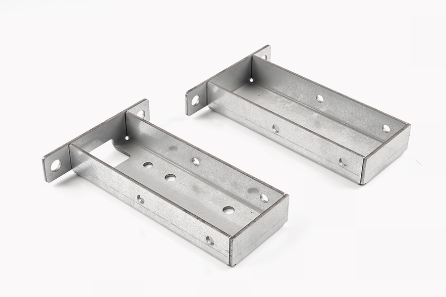
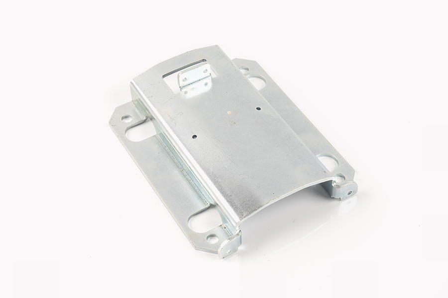
Progressive die tooling suits small to medium components featuring complex planar outlines, multiple folded flanges, raised structural ribs, and pierced hole patterns. Common components include electrical terminals, automotive sensor brackets, appliance clips, lead frames, engine shims, and structural structural connectors.
Suitable materials cover cold rolled carbon steel, stainless steel grades, brass alloys, phosphor bronze, and ductile aluminum tempers. Material thickness typically stays within zero point two millimeters to three millimeters, as heavier stock increases the force required to advance the carrier strip through the die sequence.
Tooling Maintenance and Wear Factors
Because progressive dies contain numerous intricate punch inserts aligned across a lengthy die shoe, initial tooling investment costs remain significant. Tool maintenance requires precise sharpening of individual punch faces and die buttons. Modular die construction allows technicians to remove worn or damaged stations without dismantling the entire tool assembly, reducing machine downtime during long production runs.
Deep Draw Stamping
Deep draw stamping transforms flat metal sheet blanks into seamless, hollow three dimensional shapes whose depth dimension equals or exceeds their minimum lateral opening width.
Tensile Deformation and Blank Holder Dynamics
Deep drawing differs from simple shallow stretching or bending. As the round or shaped punch descends into the die cavity, it draws metal from the outer flange region into the forming zone under pure tensile stress. To prevent the surrounding circular flange from buckling or forming radial wrinkles due to high circumferential compressive stresses, a pressurized blank holder ring clamps the outer edge of the sheet against the upper face of the die plate.
The force applied by the blank holder ring must stay within a precise operational window. Insufficient blank holder pressure allows the unconstrained metal flange to wrinkle, causing visual defects and potential die jams. Excessive blank holder pressure restricts material flow into the die cavity, inducing extreme tensile stresses along the vertical sidewalls of the drawn container, which leads to localized thinning and structural tearing.
Wall Thinning and Material Flow Control
During the drawing sequence, material experiences significant dimensional transformation. The bottom base of the container retains its original sheet thickness, while the vertical sidewalls undergo severe stretching and thinning. The radius between the container floor and vertical wall experiences peak tensile stress, making it the most vulnerable location for material necking and failure.
Calculating appropriate draw ratios dictates process success. The reduction ratio compares the initial blank diameter to the final punch diameter. If a single drawing stroke exceeds safe deformation limits for a specific material grade, fabricators implement multi stage drawing sequences. Redraw stations progressively reduce shell diameter while increasing overall cylinder height across successive press operations.
Applications for Enclosures Cylinders and Deep Cavities
Deep draw techniques produce seamless, leak tight hollow vessels requiring high structural integrity without welded joints. Typical products manufactured via deep draw stamping include automotive oil pans, fuel tanks, beverage containers, fire extinguisher bodies, battery enclosures, medical pump housings, compressed gas cylinders, and stainless steel kitchen sinks.
Ductile alloys with high strain hardening capabilities excel in deep draw applications. Deep drawing quality aluminum alloys, low carbon drawing steel grades, copper, brass, and austenitic stainless steels demonstrate the localized elongation capacity necessary to endure severe plastic deformation without fracturing.
Tooling Design and Wrinkling Prevention
Deep draw tooling incorporates generous draw radiuses on both the punch tip and die cavity entry lips. Sharp corners concentrate localized stress, accelerating material failure. Polished draw die surfaces featuring low surface roughness values reduce friction, encouraging smooth material flow under high blank holder forces. Interstage annealing heat treatments are implemented during complex multi draw operations to relieve work hardening stresses and restore material ductility before subsequent drawing steps.
Transfer Die Stamping
Transfer die stamping handles large, heavy, or geometrically complex sheet metal parts that cannot remain attached to a continuous carrier strip during processing.
Mechanical Transfer Arms and Station Separation
Unlike progressive die systems where continuous coil stock advances through connected stations, transfer die stamping processes separate individual metal blanks. Raw material enters the press as pre cut flat blanks or gets blanked directly from a coil at the first station. Once separated, individual parts move from station to station via synchronized mechanical transfer rails equipped with vacuum cups, magnetic grippers, or mechanical fingers.
The mechanical transfer mechanism lifts, advances, lowers, and places individual parts into individual die stations positioned along the press bed. Because each station houses an independent die block, parts can be elevated, rotated, or reoriented between strokes, allowing complex three dimensional operations that would be impossible inside a constrained progressive carrier strip.
Processing Large Complex Metal Components
Transfer die processes accommodate large structural components whose weight or dimensions render continuous strip feeding impractical. Removing the carrier strip eliminates the risk of strip distortion or feed jamming during heavy forming strokes.
Because individual stations function independently, transfer presses exert massive total tonnages across wide bolster areas. Fabricators utilize transfer stamping for structural automotive body panels, chassis cross members, appliance cabinet shells, heavy machinery enclosures, and large structural brackets.
Freedom of Part Orientation and Secondary Operations
The separation of individual workpieces unlocks significant geometric design flexibility. Mechanical transfer systems can tilt a component between stations to allow side piercing, angled cam trimming, reverse flanging, or bottom coining without requiring complex multi axis die mechanisms inside a single station.
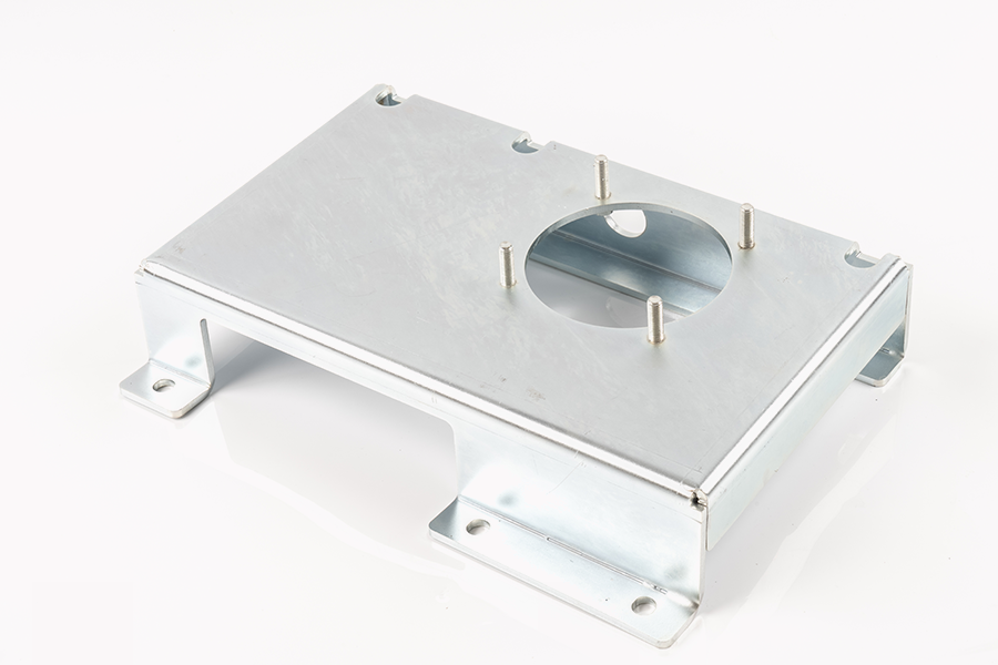
Furthermore, secondary hardware insertion can be integrated directly into the transfer press sequence. Threaded studs, nuts, and bushings can be automatically pressed into punched holes at intermediate transfer stations, delivering fully assembled structural parts directly off the press line.
Cost Parameters for Medium and Large Parts
Transfer die tooling requires substantial capital investment due to the large size of individual die blocks and the mechanical complexity of transfer automation systems. However, material efficiency stays high. By using pre cut tailored blanks or optimized blanking dies upfront, raw material scrap generation remains significantly lower than progressive die layouts that require continuous carrier web borders.
Four Slide Stamping
Four slide stamping, also referenced as multislide forming, is a specialized metalworking process that operates outside traditional vertical press parameters to shape intricate wire and narrow metallic strip stock.
Multi Directional Forming Capabilities
Traditional press systems deliver vertical impact force along a single axis perpendicular to the press bolster. Four slide machines utilize a horizontal layout featuring four orthogonal slide shafts mounted ninety degrees apart around a central vertical forming mandrel. Cams, gears, or servo actuators drive four distinct tool slides, enabling them to strike the raw material from four different horizontal directions in a synchronized timing sequence.
Raw strip or wire stock feeds horizontally into the machine center, where a primary mechanism cuts the material to accurate length. The four surrounding tool slides then advance sequentially or simultaneously, wrapping the metal around the central mandrel to create complex loops, reverse bends, closed rings, and intricate folds.
High Precision Bending for Complex Wire and Strip Shapes
The orthogonal orientation of four slide tooling allows complete three dimensional manipulation of narrow metallic strips and solid wires. Form slide movements can be timed to execute intricate folding operations that would require complex cam driven sub assemblies inside standard vertical stamping dies.
Because tools approach the workpiece from four independent quadrants, components with closed cylindrical loops or interlocking tabs can be formed smoothly around the central mandrel. Once forming operations conclude, the central mandrel retracts or an ejector pin strips the finished component away, dropping it into a collection hopper.
Operational Efficiency for Small Intricate Components
Four slide manufacturing delivers exceptional processing speeds for small intricate components, frequently achieving production rates ranging from eighty to over three hundred pieces per minute. The process demonstrates high material efficiency because initial stock width equals the exact finished width of the component, eliminating side scrap trimming.
Common items manufactured on four slide machinery include spring clips, electronic connector contacts, retaining rings, surgical clips, battery terminals, wire handles, and complex optical frame brackets.
Reduced Tooling Costs and Setup Flexibility
Four slide tooling blocks are significantly smaller and less costly to fabricate than large progressive die sets. Tooling engineers adjust forming sequences by altering cam timing disks or reprogramming servo motion profiles rather than remachining heavy tool steel plates. This flexibility lowers initial tooling investment, making four slide forming accessible for medium production volumes as well as high volume manufacturing runs.
Comprehensive Comparison of Primary Stamping Processes
Choosing the appropriate manufacturing methodology requires evaluating production volumes, geometry, material utilization, and tooling budget limits. The following comparison highlights key operational characteristics across all four primary metal stamping types.
Trade Off Analysis: Tooling Cost Versus Unit Output
High initial tooling expenditures inherent to progressive and transfer die systems are amortized over long production runs containing hundreds of thousands or millions of parts. For smaller production runs, the lower initial tooling entry threshold of four slide systems or simplified modular tooling provides a more economical path to production despite slightly lower overall line speeds.
Trade Off Analysis: Material Efficiency and Scrap Control
Raw material cost represents a substantial portion of total component expense in sheet metal fabrication. Progressive dies retain web borders to transport parts, which increases material waste. Transfer dies and four slide machines optimize raw blank dimensions, minimizing trim scrap and reducing overall component material costs over the product lifecycle.
Critical Engineering Selection Criteria for Stamping Metal Parts
Selecting the correct stamping methodology requires thorough evaluation of structural, mechanical, and economic parameters prior to final tooling construction.
Production Volume Demands and Amortization
Project volume strongly influences process selection. High volume automotive or consumer electronics contracts justify high capital expenditures for complex progressive or transfer tooling dies because low cycle times and reduced labor content yield low cost per unit over time. Conversely, low or moderate volume contracts favor processes with lower tooling entry barriers to avoid excessive upfront capital drag.
Geometric Complexity and Feature Location
Part geometry dictates mechanical movement requirements. Flat components featuring internal punch holes, simple lance tabs, and shallow flanges align perfectly with progressive die capabilities. Deep hollow shapes require the controlled metal drawing mechanics of deep draw presses. Multi axial wire shapes or intricate closed loops with overlapping bends point directly toward four slide manufacturing platforms.
Material Ductility and Grain Direction Orientation
Material mechanical properties determine allowable deformation severity. High strength low alloy steels exhibit higher yield strength and pronounced springback, requiring specialized coining or overbending stations within die sets. Soft copper and aluminum alloys accommodate severe plastic deformation easily but require gentle handling to prevent surface marring. Aligning major bend lines perpendicular to sheet rolling grain direction prevents premature material cracking across tight bend radii.
Secondary Operations and Assembly Integration
Integrating secondary operations inside the primary press line dramatically reduces overall manufacturing lead time. Progressive and transfer die systems can incorporate inline tapping modules to cut internal screw threads, insert clinch fasteners, or apply optical vision verification checks during the press stroke, delivering complete ready to ship components directly from the press bed.
Quality Control Protocols in Metal Stamping Operations
Maintaining high dimensional quality across massive production volumes requires robust quality control protocols, real time process monitoring, and systematic die maintenance programs.
In Process Sensor Monitoring and Tonnage Protection
Modern stamping presses utilize piezoelectric tonnage sensors mounted on press frames and die shoes to measure real time force curves during every stroke. Deviation from baseline force profiles alerts operators to material thickness variations, slug pulling problems, tool punch breakage, or inadequate die lubrication. In die vision sensors verify part ejection and hole placement before the press ram descends for the next cycle, preventing expensive die crash damage.
Dimensional Accuracy Verification and Coordinate Measurement
Quality assurance teams conduct periodic dimensional inspections using automated Coordinate Measuring Machines, optical shadowgraphs, and laser scanning systems. Key features such as hole location centerlines, flange angles, burr heights, and profile tolerances are tracked using Statistical Process Control charts to detect dimensional drift before parts fall outside engineering drawing specifications.
Common Stamping Defect Mitigation Strategies
Preventing component defects requires continuous monitoring of raw material quality and die wear patterns.
-
Springback Control: Metal naturally flexes backward slightly after punch release due to residual elastic stress. Tooling engineers incorporate localized stress relief features, bottom coining punches, or calculated overbending angles inside die cavities to compensate for material springback.
-
Burr Height Reduction: Punching and blanking operations create micro burrs along sheared edges as tool steel cutting edges dull. Maintaining precise punch to die clearances and establishing scheduled punch sharpening routines keeps burr heights well within allowable engineering limits.
-
Galling and Surface Scoring Prevention: Excessive friction during heavy forming causes local material transfer from raw sheet stock to tool steel surfaces. Applying advanced PVD tool coatings like titanium nitride alongside high performance lubricants prevents surface scoring and extends die life across demanding production schedules.

 Company Profile
 +86-189-57809418
 Zouxi Village, Tangxi Town, Yinzhou District, Ningbo City, Zhejiang Province, China
Copyright © Ningbo Mingli Electric Technology Co., Ltd. All rights reserved. Custom Hardware Parts Maunfacturers
