


 Eng

 中文简体

 Home / News / Industry News / High Precision Stamping: Tolerances, Tooling, Materials and Sourcing Guide
High Precision Stamping: Tolerances, Tooling, Materials and Sourcing Guide
 2026.10.22
 Industry News
A 0.4 mm stainless steel contact spring for a miniature circuit breaker carries ±0.03 mm on the contact gap, a 0.02 mm burr limit and a flatness callout of 0.05 mm across a 25 mm span. The press that forms it might be a 45-tonne machine — unremarkable on a specification sheet. What actually makes that part "high precision" is everything surrounding the press: the strip layout, the die clearance, the material certificate, the in-die sensor that stops the stroke when a slug fails to eject, and the dimensional report that travels with the shipment.
So the working definition is this: high precision stamping is a progressive-die process in which dimensional tolerance, burr height, flatness and lot-to-lot repeatability are controlled tightly enough that the part can go straight into assembly without sorting, rework or 100% inspection. Everything that follows explains how that control is engineered, what it costs, where it quietly fails, and how a buyer can specify and qualify it without discovering problems six weeks into production.
Three conclusions are worth stating before the detail:
- Precision is designed into the part and the tool, not dialled in on the press. Roughly 70–80% of the achievable tolerance is fixed by part geometry, material choice and die design before the first stroke.
- Tolerance and cost are not linearly related. Tightening a non-critical dimension from ±0.20 mm to ±0.05 mm is nearly free; tightening a critical one from ±0.05 mm to ±0.02 mm can add 30–60% to tooling cost.
- Most quality escapes in stamped components trace back to material variability and tool wear, not to machine accuracy. Buyers who manage those two variables rarely have tolerance arguments.
What High Precision Stamping Means in Practice
There is no universal standard that defines "high precision" in stamping. Different suppliers draw the line in different places, which is why a purchase order that simply says "high precision" is almost meaningless. What matters is the tolerance band the tooling is built to hold across the production run, not just on the first-off sample.
A useful way to frame capability is by tolerance class, since the class drives tooling budget, inspection method and the volume at which the economics still work.
| Class | Critical feature tolerance | Burr height (typical) | Flatness over 100 mm | Representative parts |
|---|---|---|---|---|
| General sheet metal | ±0.20 mm | ≤0.10 mm | 0.30 mm | Brackets, covers, chassis panels, mounting plates |
| Precision stamping | ±0.05 mm | ≤0.05 mm | 0.10 mm | Connector shells, shielding cans, terminals, busbar supports |
| High precision stamping | ±0.02 mm, down to ±0.01 mm on selected features | ≤0.02–0.03 mm | 0.05 mm | Contact springs, relay components, motor laminations, sensor housings, small precision assemblies |
Two things are worth noting in that table. First, the burr requirement is usually the harder constraint in practice. A 0.05 mm burr limit on a 0.3 mm thick part sounds modest until you account for punch wear across 500,000 strokes. Second, the "selected features" qualifier matters: no tool holds ±0.01 mm everywhere, and a drawing that demands it globally will be quoted either very high or not at all.
Precision also extends beyond the two-dimensional drawing. A part can be dimensionally perfect and still fail assembly because of twist, camber, edge condition or residual stress that opens up after plating. Experienced buyers specify those characteristics explicitly.
Precision Is Decided Before the Press Starts
When a stamped part drifts out of tolerance, the instinctive question is "what is wrong with the machine?" It is almost never the machine. Four levers control the outcome, and they are set in this order.
Part design and design for manufacture
The most common cause of an unquotable high precision stamping project is a drawing inherited from a machining or die-casting process. Machined parts routinely call for sharp internal corners, deep narrow pockets and wall thickness variation that a stamping die cannot reproduce economically. A stamping-friendly revision — added relief, adjusted bend radii, reoriented features so they sit in one station — often removes cost without touching function.
Minimum bend radius is a good early check. For mild steel, an inner radius of 0.8–1.0 times material thickness is achievable without cracking; for austenitic stainless, allow roughly 2 times thickness because of work hardening and springback. Anything tighter needs either a different material, annealing between operations or a redesign.
Die clearance and strip layout
Cutting clearance is typically 5–8% of material thickness per side for carbon steel, slightly less for stainless and brass, slightly more for aluminium. Too little clearance raises punching force, accelerates wear and produces secondary shear and a taller burr; too much produces rollover, a rough fracture face and a burr that bends rather than shears.
Strip layout governs repeatability as much as the die itself. Pilot holes that locate every station, adequate carrier width, consistent bridge widths between parts, and balanced material flow around the strip all reduce positional error. In high precision work, the strip is often designed so that critical features are formed in the same station rather than re-registered downstream — every re-registration is an opportunity for stack-up error.
Material consistency
A die built for a 180 HV substrate will produce different dimensions when a coil at 220 HV arrives, because springback scales with yield strength. Coil-to-coil hardness variation of 20 HV is common in commercial grades and is enough to shift a bend angle by 0.5–1.5 degrees. Buyers purchasing high precision stampings should expect incoming material certificates with hardness and mechanical properties, and suppliers should be sampling them. Where the requirement is genuinely tight, specify a hardness range rather than just a grade.
Process control on the floor
Dies wear. A progressive die running carbon steel typically needs regrinding every 100,000–300,000 strokes depending on thickness and coating; stainless is harder on tooling. What separates a reliable high precision supplier is a regrind schedule driven by measured burr height and part dimension, not by a failure. In-die sensors for slug detection, strip position, misfeed and pilot engagement are standard on serious tooling because they convert a scrap event into a stopped press rather than 5,000 suspect parts.
The Process Chain Behind a High Precision Stamped Part
High precision stamping is rarely a single operation from coil to shipping box. Understanding the chain helps a buyer see where cost sits and where risk hides.
Blanking, piercing and forming
A progressive die combines blanking, piercing, notching, bending, drawing and coining across 6–20 stations. Each station performs one increment of the geometry, and the part stays attached to the strip until the final cut-off. The precision advantage comes from never releasing the part: it is never re-fixtured, so datum strategy is maintained by the tool rather than by an operator.
In-die functions
Modern high precision tooling frequently includes functions that used to be secondary operations. In-die tapping, in-die riveting, in-die staking, in-die laser cutting for features that would otherwise require a separate pass, and in-die measurement of a critical dimension all reduce handling. Handling is where precision is lost — every time a part leaves one machine and enters another, a new fixture and a new stack of tolerances appear.
Secondary operations and assemblies
Not everything can or should be done in the die. Deburring, tumbling, thread forming, welding, insertion of plastic overmoulds, and assembly of several stamped parts into a sub-assembly are common downstream steps. When a component needs two stamped halves, a weld, a threaded insert and a plastic element, consolidating that work with one supplier removes the tolerance stack that appears when three vendors each work to their own interpretation of the drawing.
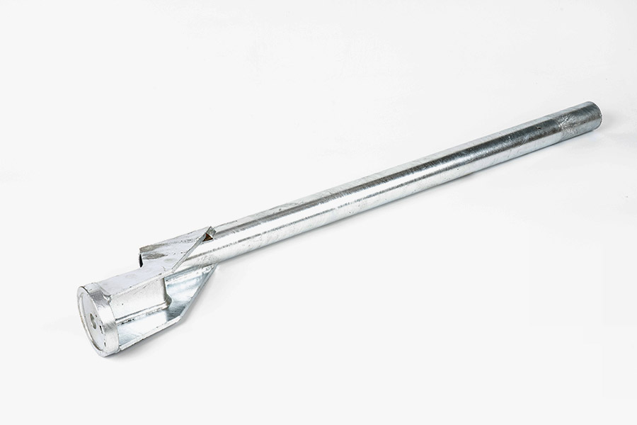
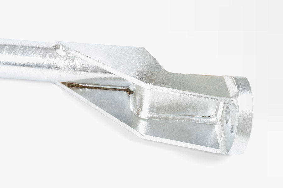
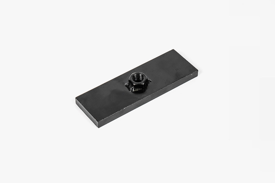
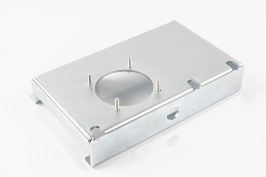 Custom Fabricated Assemblies and Sub-AssembliesCustom fabricated assemblies and sub-assemblies that consolidate stamping, welding, fastener installation and finishing to reduce tolerance stack from multiple vendors.View Product →
The practical rule: if the assembly has more than three components and the fit between them is functionally critical, source the assembly rather than the individual parts. Dimensional arguments between two suppliers who each claim to be within their own tolerance are expensive to resolve.
Material Choice Sets the Tolerance Ceiling
No die design compensates for an unsuitable substrate. Material determines springback, achievable burr, tool wear rate, and how much the part will move after plating or heat treatment.
| Material | Typical thickness | Formability | Corrosion resistance | Where it fits |
|---|---|---|---|---|
| Cold-rolled carbon steel (SPCC / DC01) | 0.2–3.0 mm | Excellent | None without coating | Internal brackets, structural parts, cost-sensitive components |
| Electro-galvanised steel (SECC) | 0.3–2.0 mm | Good | Moderate | Electrical enclosures, chassis, hardware |
| Hot-dip galvanised steel (SGCC) | 0.4–3.0 mm | Good | Good | Outdoor housings, structural hardware |
| Stainless 301 / 304 | 0.1–2.0 mm | Moderate, high springback | Excellent | Springs, contacts, appliance and food-equipment parts |
| Stainless 316 | 0.2–1.5 mm | Moderate | Very good, chloride resistant | Marine, chemical and medical housings |
| Aluminium 5052 / 1060 | 0.3–3.0 mm | Good, low springback | Good when anodised | Lightweight housings, heat sinks, covers |
| Brass C2680 / copper C1100 | 0.1–1.5 mm | Excellent | Good | Terminals, busbars, contacts, conductive parts |
| Spring steel 65Mn / 301 | 0.1–1.2 mm | Fair, requires stress relief | Poor without coating | Clips, springs, retaining features |
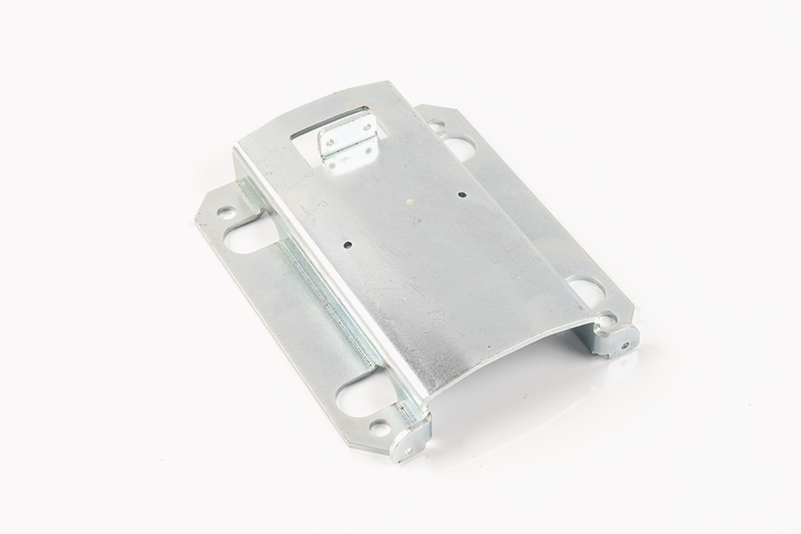
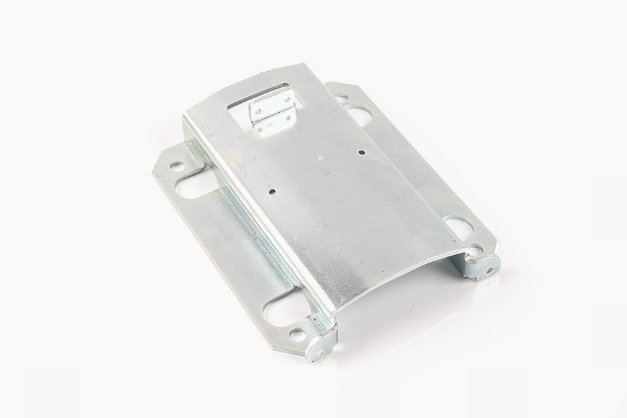
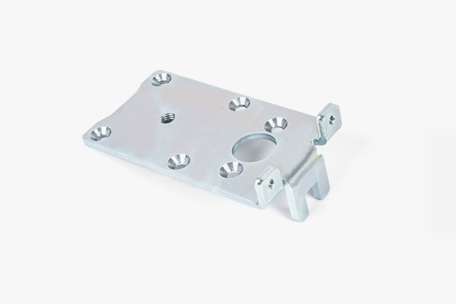
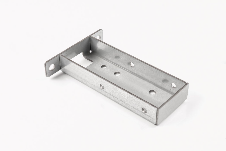 Stamping Metal Parts for Precision ApplicationsPrecision stamped metal parts for automotive, electronic, appliance and new energy equipment, with dimensional accuracy, strength and flatness suited to frames, housings and connectors.View Product →
Two material decisions cause more rework than any others. The first is substituting a "close enough" grade to save cost: SECC in place of SPCC changes the surface condition and the friction in the die, and can shift formed dimensions by several hundredths of a millimetre. The second is ignoring grain direction. Bending parallel to the rolling direction produces cracking at tighter radii than bending across it, so a part that forms perfectly in one orientation may fail when the coil is rotated.
Thickness tolerance in the raw coil is another quiet contributor. Commercial coil is commonly supplied to ±0.05 mm or ±10% of nominal, whichever is greater. On a 0.5 mm part demanding ±0.03 mm overall height, the coil tolerance alone can consume the entire budget. Buyers in that range should specify a tighter thickness tolerance on the material and expect to pay for it.
How Tolerance, GD&T and Inspection Fit Together
A drawing full of ±0.02 mm callouts without datums and without a stated inspection method is an invitation to dispute. Geometric dimensioning and tolerancing solves this by defining functional datums and by separating size from form, orientation and position. A position callout of Ø0.05 mm at MMC on two mounting holes, for example, tells the toolmaker exactly what the die must achieve and tells the inspector exactly what to measure — and it permits the bonus tolerance that a simple ±0.02 mm box tolerance does not.
Three practical conventions are worth agreeing with any supplier at the quotation stage:
- Which characteristics are critical, which are major and which are reference-only. Most drawings do not distinguish, so everything gets inspected and everything costs money.
- The process capability target on critical characteristics. A Cpk of 1.33 is a common baseline, 1.67 for automotive or safety-related parts.
- Whether the first article inspection is a full dimensional layout or a limited check, and whether it must be repeated after any tooling modification.
Inspection equipment should match the tolerance, not exceed it by so much that measurement cost dominates. A typical high precision workflow uses a coordinate measuring machine for first articles and complex geometry, an optical or vision system for flat features and burr, a profile projector for radii and angles, a roughness tester for edge and surface condition, and hand gauges for the high-frequency checks on the line. Hardness testing and coating thickness measurement complete the picture for parts that are heat-treated or plated.
Tolerance control on the shop floor is a statistical exercise rather than an inspection exercise. Checking every 200th part and plotting the critical dimensions shows tool wear trending long before a part goes out of tolerance, which is what allows a supplier to regrind on condition instead of on failure. For a deeper treatment of stack-up and positional error, see this explanation of controlling dimensional tolerance and form-and-position errors in high precision stamping.
Surface Finish, Plating and the Tolerance They Consume
Plating adds metal. A 10 µm zinc layer on each face grows a 0.50 mm part to 0.52 mm, which is fine for a bracket and fatal for a press-fit terminal. Buyers should state whether the drawing dimensions apply before or after finishing — most drawings do not, and the default assumption differs between suppliers.
| Finish | Typical thickness | Effect on dimensions | Considerations |
|---|---|---|---|
| Zinc electroplating | 5–15 µm | Consumes 10–30 µm of total allowance across both faces | Hydrogen embrittlement risk on high-strength spring steels; baking required |
| Zinc-nickel | 8–15 µm | Similar to zinc | Better salt-spray performance, higher cost |
| Passivation (stainless) | Under 1 µm | Negligible | Removes free iron; does not change appearance much |
| Electroless nickel | 3–25 µm | Uniform, but must be budgeted | Good wear resistance and solderability |
| Tin plating | 3–10 µm | Small but measurable on fine features | Primarily for solderability |
| Powder coat / e-coat | 40–100 µm | Significant; requires masking of critical features | Masking adds handling cost |
| Vibratory deburr / tumble | Removes 5–25 µm of edge material | Changes edge condition and can round corners | Often necessary to hold a burr callout |
The order of operations matters as much as the finish itself. Plating after forming is normal; plating before forming will crack the coating at every bend. Stress relief on spring steel should happen after forming and before plating. And where a part is both heat-treated and plated, the heat treatment may move dimensions enough to require a sizing operation afterwards.
Tooling: The Real Cost Centre
In high precision stamping, the tool is the product. The press is a commodity; the die is the intellectual property that determines whether the part is within tolerance at stroke 800,000 as well as at stroke 800. Buyers who treat tooling as an afterthought usually end up paying for it twice.
| Tool type | Stations | Economic volume | Relative tool cost | Notes |
|---|---|---|---|---|
| Single-stage | 1 | Under 5,000 pieces per year | 1× | Simple, slow, operator-dependent precision |
| Compound | 1 (blank and form together) | 5,000–50,000 pieces | 2–3× | Good for flat parts with one forming step |
| Progressive | 6–20 | 50,000 pieces and above | 5–15× | The default choice for high precision work |
| Transfer | Multiple, part carried between presses | High volume, large parts | High | Used where the part is too large for a strip |
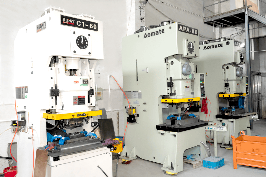 Custom High Precision Stamping ServicesHigh-precision stamping using progressive, multi-station and single-punch dies, with in-house tooling, deep drawing, punching and micro-hole capabilities for prototypes through large quantities.View Product →
Five commercial terms belong in every tooling discussion, and none of them are usually volunteered:
- Ownership. Who owns the die, and under what conditions can the buyer take it to another press? A tool that only fits one supplier's press bed has limited transfer value.
- Expected die life. Usually quoted in strokes before major refurbishment. A tool built for 300,000 strokes and one built for 3,000,000 look similar in a quotation and differ enormously in five-year cost.
- Spare and wear parts. Punches, inserts and springs are consumables. Whether they are stocked locally or shipped from overseas determines recovery time after a breakage.
- Revision policy. How many engineering changes are included, at what price, and how long a change takes to implement.
- Regrind allowance. The die must be designed with enough material to be reground several times before replacement. A tool ground to its limit on day one has no service life.
Tooling lead time for a progressive die in the 6–20 station range is typically 4–8 weeks including trial and first article approval, longer where in-die sensors, complex cams or tight position tolerances are involved. Buyers planning a product launch should treat that lead time as part of the critical path, not as a detail to be resolved after the design freeze.
When Stamping Beats Other Processes, and When It Does Not
High precision stamping is not automatically the right answer. It has a high fixed cost and a very low variable cost, which makes it unbeatable at volume and questionable below a few thousand pieces.
| Process | Setup cost | Per-part cost at 10,000 pieces | Achievable tolerance | Best volume band |
|---|---|---|---|---|
| High precision progressive stamping | High (tooling) | Very low | ±0.02 mm | 20,000 to several million |
| Laser cutting plus bending | Very low | Medium | ±0.10–0.20 mm | 1 to 5,000 |
| CNC punching | Low to medium | Low to medium | ±0.10 mm | 500 to 20,000 |
| Photo chemical etching | Medium | Medium | ±0.02 mm on thin material | 1 to 100,000, thin parts only |
| Die casting plus machining | High | Low | ±0.05 mm | 10,000 and above, 3D geometry |
The crossover point is not fixed. A simple flat bracket with two holes might justify a tool at 3,000 pieces because the tool itself is cheap. A complex progressive die with in-die tapping and eight forming stations may need 50,000 pieces before it repays the tooling. The honest way to decide is to model total cost over the expected product life, including the probability of a design change — a design change is cheap with laser cutting and expensive with tooling.
A useful middle path exists for products in the 2,000–20,000 piece range: build a progressive die with fewer stations and perform the remaining operations, such as tapping and assembly, offline until volumes justify adding them. This keeps initial tooling spend low without committing to a process that will not scale.
Defects That Show Up in High Precision Stamping
Almost every defect in precision stamping has a known cause and a known countermeasure. What varies is whether the supplier has instrumented the process to catch it early. The table below covers the failures most often found in incoming inspection.
| Defect | Usual cause | Prevention |
|---|---|---|
| Burr above limit | Worn punch or die insert, incorrect clearance | Clearance at 5–8% per side, scheduled regrind, burr height monitored as a trend |
| Dimensional drift across a run | Tool wear, strip feed error, incoming hardness variation | In-die pilot sensing, SPC on critical dimensions, material certificates with hardness range |
| Twist and flatness failure | Uneven residual stress, asymmetric forming, poor strip support | Balanced strip layout, stress-relief annealing, in-line levelling |
| Slug pulling and die marks | Insufficient slug relief, poor die geometry, weak lubrication | Slug detection sensors, vacuum extraction, die surface treatment |
| Scratches and galling | Inadequate lubrication, rough die surfaces | Coated tooling (TiN, DLC), lubricant matched to material |
| Cracking at bends | Bend radius below minimum, material too hard, grain direction | Radius at least 0.8–1.0 times thickness in mild steel, 2 times in stainless; anneal between operations |
| Plating blistering or poor adhesion | Residual stamping lubricant, insufficient pre-treatment | Specified cleaning cycle before plating, adhesion testing on first article |
One defect deserves separate mention because it is invisible at stamping and appears later: residual stress. A formed part can measure perfectly on the day of production and open or twist after plating, after heat treatment or after a few weeks in storage. Where flatness is functionally important, request a stress-relief anneal and a flatness check performed after finishing, not before.
Building an RFQ That Returns a Quotable Number
Most quotation delays are caused by the enquiry, not the supplier. A complete request for quotation for high precision stamping contains the following, and a supplier who receives it can usually respond within three to five working days.
- A 2D drawing with full GD&T, datums and a stated tolerance standard, plus a 3D model where the geometry is complex.
- Material grade, thickness with tolerance, temper or hardness range, and the applicable standard.
- Surface finish requirement, including whether dimensions apply before or after coating.
- Annual volume, order release size, and expected product life. These three numbers determine the tooling amortisation more than anything else on the drawing.
- Critical-to-function characteristics, flagged explicitly. Everything else can be treated as reference for quoting purposes.
- Quality documentation requirements: first article report, control plan, material certificates, PPAP level if applicable.
- Packaging and labelling requirements, including any returnable container scheme.
- Destination and Incoterms, since export packing and freight affect landed cost substantially.
- Target price and target production start date, if they are fixed. Suppliers will design the process around both.
The most common omission is the volume profile. A quotation built on 100,000 pieces per year and one built on 2,000 pieces per year with monthly releases differ by more than a factor of two on per-part price, because setup, tooling amortisation and inspection frequency are spread over very different quantities. Giving a single number invites a quotation for the single number, and a surprise when actual releases arrive.
Cost Structure: What You Are Actually Paying For
Understanding the cost structure makes negotiation more productive, because it moves the discussion from "reduce the price by 8%" to "which of these elements can be changed".
- Material. Usually 25–45% of piece price, driven by grade, thickness, coil width utilisation and scrap recovery value. Strip layout that reduces scrap from 30% to 22% is worth more than most price negotiations.
- Tooling amortisation. Spread across the quoted volume. This is where volume assumptions matter most.
- Press time. Strokes per minute multiplied by the number of stations the part occupies. A part that can be produced in a 12-station die running at 300 strokes per minute is dramatically cheaper than one requiring 20 stations at 120 strokes per minute.
- Secondary operations. Tapping, deburring, welding, plating and assembly are labour-sensitive and typically carry higher margins than stamping itself.
- Inspection. Often underestimated. A part with 40 toleranced characteristics inspected at every lot costs far more to release than one with four.
- Packaging and logistics. Export packing, desiccant, rust prevention and freight from port to destination add a visible percentage to landed cost, especially for low-value parts.
Two hidden costs deserve attention during negotiation. Scrap rate assumptions sit inside the piece price and are rarely disclosed; asking for the assumed scrap rate is a legitimate and revealing question. Freight consolidation is the other: a supplier located near a major container port can consolidate shipments and reduce landed cost in ways a quotation does not make visible.
Supplier Qualification: Documents to Ask For
A high precision stamping supplier should be able to produce the following without a long internal search. If any item requires escalation, that itself is information about the organisation.
- Quality management system certificate with the certification body named and the scope covering metal stamping.
- Material certificates for the specific heat or coil lot used on the first article.
- First article inspection report with measured values against every toleranced characteristic, not pass/fail ticks.
- A process control plan identifying which characteristics are checked, how often, with what instrument.
- Equipment list with press tonnage, maximum bed size, stroke rate and die height capacity — this shows whether the tooling actually fits.
- Corrective action records from recent customer issues. A supplier with no recorded issues is either new or not recording them.
- Sub-supplier list for plating, heat treatment and any outsourced operation, since most quality escapes originate outside the stamping plant.
- Sample packaging and identification standard, including lot traceability from coil to carton.
An audit or a video walkthrough is worth more than a document set. Watching how scrap is segregated, whether dies are stored on racks with maintenance records attached, and whether the inspection area is separated from the production floor tells an experienced buyer more about capability than a certificate.
Working With a Ningbo-Based Stamping Supplier
Ningbo is one of the more practical places in China to source stamped metal parts, largely because of logistics. The port handles a very high volume of container traffic, and a factory within roughly 25 km of the port can move finished goods from production line to container yard in a single day. For export programmes with tight shipping windows, that proximity removes a category of delay that inland suppliers cannot avoid.
Ningbo Mingli Electric Technology Co., Ltd. is a manufacturer and trading company established in 2017, working in stamped metal parts, sheet metal parts and fabricated assemblies, with a stated capacity of more than 5,000 tonnes per year and a team of over 50 people. The company's stated process scope covers five routes that map onto the product categories: high precision stamping for stamped metal parts, sheet metal processing for sheet metal components, and internal thread processing, welding and plastic processing supporting assembly work. Development is custom-driven — parts are built to customer drawings or samples rather than from a catalogue — and the company's stated business is export-oriented across Europe, the Americas, Southeast Asia and the Middle East.
For buyers, that profile is most useful in three situations. First, when a component has been designed in one process and needs to be optimised for stamping, since the custom development route allows early design involvement. Second, when a part requires more than one process — a stamped bracket with a tapped insert and a welded reinforcement, for example — and consolidating avoids the tolerance stack of dealing with three suppliers. Third, when volumes fall between the small-batch laser-cut range and the very high volume dedicated-tool range, where a supplier with flexible press capacity and a mix of die types can be more economical than either extreme.
The usual due diligence still applies, and none of it should be skipped on the basis of a company profile. Ask for the quality management certificate and its scope, confirm which specific certifications are held rather than assumed, request the equipment list against your part size and tonnage, and ask directly which operations are performed in-house and which are subcontracted. Ask too for the scrap rate assumption in the quotation and the regrind interval for the die that would run your part. A supplier that answers those four questions clearly is usually a supplier that controls its process.
High precision stamping rewards buyers who treat it as an engineering purchase rather than a commodity purchase. The tolerance you receive is the tolerance the tool was built to hold, and the tool reflects the drawing you supplied, the material you specified and the volume you committed to. Getting those three inputs right before the die is cut is worth more than any price negotiation conducted afterwards.
The practical sequence is short. Define critical characteristics and let the rest be reference. Choose a material grade and thickness tolerance that leave room for the process. Agree inspection method, capability target and documentation before the first article, not after the first complaint. And confirm, in writing, who owns the tool, how long it is expected to last and what happens when the design changes. Do that, and the ±0.02 mm on the drawing stops being a risk and starts being a specification.

 Company Profile
 +86-189-57809418

 Zouxi Village, Tangxi Town, Yinzhou District, Ningbo City, Zhejiang Province, China

Copyright © Ningbo Mingli Electric Technology Co., Ltd. All rights reserved. Custom Hardware Parts Maunfacturers
