


 Eng
Eng 
 中文简体
中文简体
 Home / News / Industry News / Rapid Sheet Metal Prototyping: Processes, Materials, and Partner Selection
 Rapid Sheet Metal Prototyping: Processes, Materials, and Partner Selection
 2026.09.17
 Industry News
A design review meeting ends with an uncomfortable deadline: the sheet metal enclosure for the new industrial sensor must be physically validated before the next milestone. The tooling lead time alone is eight weeks, and the customer cannot wait that long to see a part. This scenario repeats daily in product development teams across the automotive, medical, consumer electronics, and industrial equipment sectors. The solution is rapid sheet metal prototyping—a manufacturing approach that delivers functional metal parts in days rather than weeks, using the same production-equivalent processes that will eventually make the part in volume.
What Is Rapid Sheet Metal Prototyping?
Rapid sheet metal prototyping is the small-batch fabrication of sheet metal parts using production-representative processes such as laser cutting, CNC punching, bending, welding, and surface finishing. It lets engineers verify geometry, assembly fit, mechanical performance, and manufacturability before committing to production tooling or large-quantity procurement.
The word "rapid" refers to the compressed delivery timeline. A typical sheet metal prototype order is quoted and shipped in one to two weeks, and many suppliers can turn around single-piece orders in as little as two to five days when the design is manufacturing-ready. Fast delivery is not just a convenience; it changes how engineers approach design validation. Instead of treating the prototype as an afterthought, teams can run multiple design iterations in the same time a traditional tooling-based approach would need for a single sample.
Rapid sheet metal prototyping differs from conventional prototyping in three concrete ways:
- Production-equivalent processes are used, so the prototype's mechanical properties, surface finish, and dimensional behavior match the final part.
- No hard tooling is required, so setup cost remains low even for single-piece orders.
- The same supplier can often continue into low-volume production, eliminating the need to transfer designs between separate prototype and production shops.
In practice, this means you can hold a genuinely representative part in your hand, test it, show it to your customer, and then proceed to volume production with confidence that the fabricated part will behave as expected.
Why Speed Matters in Product Development
Speed in prototyping is not about impressing anyone with fast turnaround. It is about reducing risk and preserving flexibility during the most uncertain phase of a product's life. Engineering changes become exponentially more expensive as the product moves from concept to tooling to production: a design change at the prototype stage costs hours; the same change after hard tooling is cut costs weeks and thousands of dollars in reworked dies.
Consider a typical enclosure project. The mechanical engineer needs to confirm three things before approving the design: that the PCB and connectors fit inside the enclosure, that the mounting points align with the chassis, and that service technicians can access internal components without damaging the sheet metal. None of these can be fully verified from a CAD model alone. A sheet metal prototype made in the actual material and thickness reveals interference, clearance, and assembly sequence issues that no virtual simulation can reliably predict. Springback, bend allowance, heat distortion from welding, and fastener clearance are all physical phenomena that only appear when material is actually formed.
There is also the commercial dimension. Every week of unvalidated design is a week of added time-to-market risk. In industries where product life cycles are measured in months rather than years, delaying a launch to wait for tooling is rarely acceptable. Rapid sheet metal prototyping compresses that validation gap and lets procurement teams place production orders with confidence.
A practical rule used by experienced engineers is to order sheet metal prototypes as early as the CAD model reaches a "design freeze for review" status, even if minor changes will follow. Early prototypes surface dimensional conflicts quickly, and because redesign iterations are inexpensive at the prototype stage, the total development time actually shrinks. Waiting until the design is one hundred percent finished before ordering prototypes usually means the first prototype immediately uncovers problems—and the second round starts from that point anyway.
Core Processes Behind Rapid Sheet Metal Prototyping
To evaluate whether a supplier can support rapid sheet metal prototyping, you need to understand the individual processes that turn a flat sheet into a finished part. Each process has specific capabilities, tolerances, and constraints that affect part design and supplier selection.
Laser Cutting
Laser cutting is usually the first operation in a sheet metal prototype. A focused laser beam cuts the outline of each flat blank from a sheet of material, with kerf widths well below 0.5 mm and positioning tolerances of roughly ±0.1 to ±0.2 mm depending on material type and thickness. Modern fiber lasers cut mild steel, stainless steel, aluminum, copper, and brass with minimal tooling requirements. The absence of mechanical force means thin and fragile features can be cut without distortion.
For prototype quantities, laser cutting replaces the stamping dies that would be needed in mass production. This is the main reason a sheet metal prototype can be delivered in days instead of the weeks required to build a blanking die. If the part will later be produced by stamping, the laser-cut prototype still provides a valid representation of bend formability, edge quality, and hole positions for functional testing.
CNC Turret Punching
CNC turret punching uses a punch and die set to create holes, slots, louvers, embosses, and other features by mechanical deformation. It is efficient when a part contains many identical geometric features, such as ventilation grids, cable entries, or connector cutouts. Because punching is a shearing process, hole edges are clean and consistent, and tolerances of ±0.1 mm are typical.
However, punching requires dedicated tooling for each feature geometry, so it becomes more attractive when the prototype order reaches a quantity of several hundred parts, or when the design includes repetitive patterns that would be slow to laser-cut individually. Many rapid prototyping shops combine laser cutting for the outside contour with CNC punching for repeated internal features, achieving a balance of speed and cost.
Bending and Forming
Bending is where a flat blank becomes a three-dimensional part. CNC press brakes use a punch and die set to bend the sheet to a specified angle and radius. Standard V-die bending handles a wide range of material thicknesses, typically from 0.5 to 6 mm, and the achievable angular tolerance is generally about ±1 degree, while positional tolerance across a bend line is around ±0.5 mm.
The K-factor and springback of the material must be accounted for in the bend calculation. An experienced supplier will anticipate springback and adjust the bend angle accordingly. This is one of the areas where a supplier's sheet metal processing experience directly affects prototype quality. A prototype that returns a bent flange with excessive springback or cracking at the bend radius is not just a nuisance; it indicates that the design cannot be produced repeatably at scale.
Welding and Joining
Welding joins multiple sheet metal components into an assembly. TIG welding produces clean and controlled welds on stainless steel and aluminum with minimal spatter, while MIG welding offers higher deposition rates for mild steel. Laser welding is also increasingly available and creates narrow, precise seams that require minimal cleanup. For assembled prototypes, welding must be planned with distortion in mind; fixtures are used to hold parts in position during welding, and consistent quality depends on the welder's skill and the shop's experience.
For rapid prototypes, welding assembly is also the point where internal thread processing and other secondary operations are often integrated. A designer may specify weld nuts, clinch studs, or tapped holes to be added after joining. Choosing a supplier that controls these secondary operations in-house reduces logistics complexity and shortens turnaround.
Surface Finishing
Surface finishing affects both appearance and corrosion resistance. Powder coating provides a durable, even finish over the entire part, hiding minor surface scratches but adding around 50 to 100 μm of coating thickness, which can affect tight fits. Anodizing is common for aluminum parts and provides a hard, corrosion-resistant oxide layer, but it changes color and can be applied in thicknesses from 5 to 25 μm. Chromate conversion and electroplating are options for specific performance requirements.
A rapid prototyping partner should be able to finish prototype parts using the same process you plan to specify in production. This is essential for verifying that the finish does not interfere with tolerances, electrical grounding, or assembly clearance. It also lets you confirm the final aesthetic appearance before the design is locked.
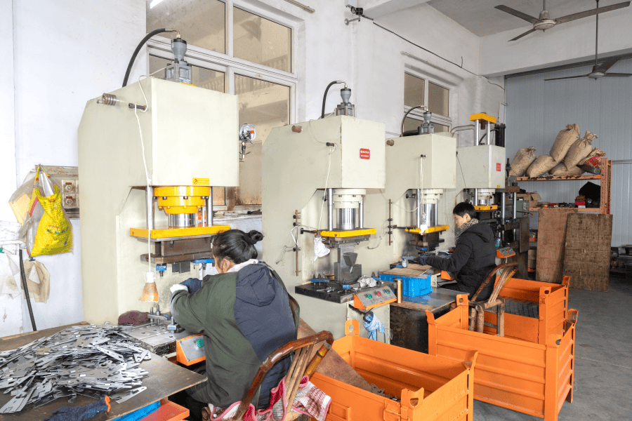 Sheet Metal Processing and Stamping Services for PrototypesThis manufacturer offers stamping, bending, and finishing services that help verify production intent. Reviewing their capabilities is useful when confirming surface finish and material behavior before locking your design.View Product →
Materials for Rapid Sheet Metal Prototypes
Material selection for prototypes should mirror production intent. If the production part will be formed from 1.5 mm cold-rolled steel, the prototype should be formed from the same gauge and grade. Prototypes made from a different material or thickness can mislead you on bend radii, springback, weight, heat dissipation, and corrosion resistance. The table below summarizes common sheet metal materials used in rapid prototyping.
| Material | Common Grades | Strength and Formability | Typical Prototype Uses |
|---|---|---|---|
| Aluminum | 5052-H32, 6061-T6 | Good strength-to-weight ratio, excellent formability, corrosion-resistant | Enclosures, brackets, heat sinks, chassis, aerospace and automotive components |
| Cold-rolled steel | SPCC, DC01, A1008 | High strength, economical, easy to form, excellent for painting and plating | Structural parts, panels, automotive brackets, electrical enclosures |
| Stainless steel | 304, 316L | High strength, excellent corrosion resistance, work-hardens during forming | Medical devices, food processing equipment, marine hardware, outdoor enclosures |
| Copper and brass | C110, C260, C280 | Excellent electrical and thermal conductivity, aesthetic appearance, good formability | Busbars, electrical terminals, decorative panels, RF shielding |
| Galvanized steel | DX51D, SGCC | Zinc coating provides corrosion protection, economical, formable with care | Outdoor enclosures, HVAC ducting, agricultural equipment |
Thickness is another critical parameter. Sheet metal prototyping typically covers material from 0.5 mm to 6 mm. Below 0.5 mm, the material becomes difficult to handle and may require specialized processes. Above 6 mm, bending forces increase significantly and the part may be better machined. When you request a quote, specify the material grade and thickness you intend to use in production, and expect the supplier to advise you if that combination is not recommended for the geometry.
One procurement caution: if you select a material that is not stocked by the supplier, lead time will increase because the supplier must order coil or sheet from a mill or distributor. Standard materials such as 5052 aluminum, SPCC steel, and 304 stainless steel in common gauges are usually in stock at established shops, which keeps the prototype within the promised turnaround window.
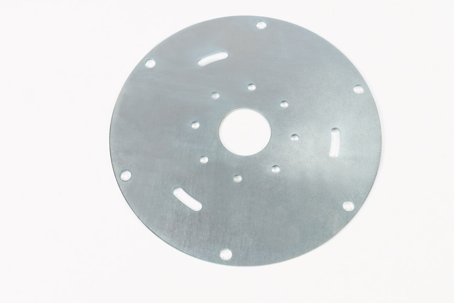 Sheet Metal Fabrication Partner for Prototype ValidationAs a full-service fabrication provider, this company supports cutting, bending, and assembly. Their page is relevant for sourcing standard stocked materials like steel or aluminum to keep prototype lead times short and realistic.View Product →
Rapid Sheet Metal Prototyping vs. 3D Printing vs. CNC Machining
Engineers often ask whether 3D printing or CNC machining should replace sheet metal fabrication for prototypes. The answer depends on what you need to validate. Sheet metal prototyping is the only one of the three that produces parts with the same grain structure, thickness, and forming behavior as production sheet metal parts. If your design is an enclosure, a bracket, or a chassis that will eventually be stamped or folded from sheet, a sheet metal prototype gives you realistic mechanical data.
| Criterion | Sheet Metal Prototyping | 3D Printing | CNC Machining |
|---|---|---|---|
| Material fidelity | Same sheet material as production | Usually plastic or costly metal powder | Solid billet, not representative of sheet behavior |
| Wall thickness | 0.5 to 6 mm, uniform sheet | Variable, limited by process resolution | Thin walls difficult and expensive |
| Mechanical properties | Production-equivalent | Layer-dependent, weaker along Z axis | Production-grade, but may retain machining stresses |
| Best for | Enclosures, brackets, chassis, panels | Complex internal cavities, ergonomic models | Precision blocks, gears, thick parts, tight tolerances |
| Lead time | 2 to 10 days typical | 1 to 5 days typical | 3 to 10 days typical |
| Unit cost at low quantities | Moderate | Low to moderate | Higher due to machining time |
| Tooling requirement | No hard tooling | No tooling | No tooling |
3D printing is the faster option when you need a visual concept model or a complex internal lattice structure that sheet forming cannot achieve. But printed parts do not bend like sheet metal, do not have the same surface finish, and are usually not structurally equivalent. CNC machining from solid billet can produce accurate parts with excellent tolerances, but machining a thin-wall enclosure from a solid block is wasteful and does not replicate the behavior of a folded sheet, particularly at corners and flanges where material thinning occurs during forming.
In a typical workflow, engineers use 3D printing for early ergonomic and packaging studies, then switch to rapid sheet metal prototyping once the design approximates final geometry. This sequence gives them the best of both worlds: fast concept iterations followed by production-equivalent validation.
Design for Manufacturability: Principles That Keep Prototypes on Schedule
The speed of rapid sheet metal prototyping depends largely on the quality of the CAD file you send. A design that violates basic sheet metal rules will generate quoted delays, email exchanges with the supplier, and rework. Applying design for manufacturability (DFM) principles before submitting the file is the most effective way to keep your prototype on schedule.
Bend Radius and Flange Height
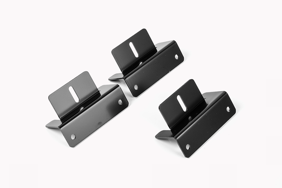
Use a bend radius that matches the material thickness and tooling standards. A common rule is an inside bend radius equal to the material thickness. If you specify a radius larger than equipment tooling, the supplier must select a custom tool, increasing cost and lead time. The minimum flange height should be at least twice the material thickness plus the bend radius; if the flange is too short, the sheet will slip in the die and the bend angle will be inconsistent.
Hole-to-Bend Distance
Holes and cutouts located too close to a bend line can deform during forming. The general guideline is to keep the edge of any hole at least twice the material thickness plus the bend radius away from the bend line. If a hole must be closer, it is preferable to cut it after forming, which the supplier can do as an additional operation.
Minimum Feature Sizes
Laser-cut holes should be no smaller than roughly the material thickness, with a practical minimum of 0.8 to 1.0 mm in thin sheet. Slots should have a width of at least 1.5 times the material thickness. For punched features, follow the tooling catalog of the supplier; standard round punches are available in common diameters, while custom punch shapes add cost and lead time.
Avoid Over-Specifying Tolerances
One of the most common delays in prototyping is a drawing covered with tight tolerances that are not actually required for function. Every tight tolerance forces the manufacturer to use more expensive methods and more inspection time. Specify tolerances only on critical interfaces such as mounting holes, mating flanges, and guide slots. Leave general dimensions to the manufacturing standard of ±0.5 mm for bending and ±0.2 mm for cutting, which keeps costs low and production schedules predictable.
When you send a design to a supplier with real sheet metal experience, they will provide DFM feedback that flags geometry that cannot be formed, features that require secondary operations, and opportunities to reduce cost. Accepting this feedback is part of the rapid prototyping workflow; it is far cheaper to adjust the CAD file than to discover the problem in a physical prototype.
Tolerances, Quality Control, and Inspection
Understanding realistic tolerances is essential for both the design and the procurement decision. Sheet metal is not a precision machining process; it is a forming process with inherently larger tolerances, especially at bends and welded joints. The table below shows typical values that experienced shops can achieve.
| Process | Typical Tolerance | Practical Notes |
|---|---|---|
| Laser cutting | ±0.1 to ±0.2 mm | Depends on material type and thickness; thinner sheet achieves tighter values |
| CNC punching | ±0.1 mm | Hole-to-hole spacing well controlled |
| Bending | ±0.5 mm positional, ±1 degree angular | Springback compensated by experienced operators |
| Welding assembly | ±0.5 to ±1.0 mm | Depends on fixture design and weld distortion management |
| Hardware insertion | ±0.15 mm | For clinch nuts, standoffs, and studs |
Quality control starts with the raw material. A reliable supplier will verify material grade and thickness certificates, especially for stainless steel and aluminum, where using the wrong temper can cause cracking during bending. After fabrication, inspection typically includes dimensional measurement with calipers, gauges for hole positions, and a fixture check for assembled prototypes. For critical dimensions, a coordinate measuring machine provides higher precision and an objective record for the first article inspection report.
Another quality consideration is consistency across the process. Dimensional tolerance and form-and-position errors during high-precision stamping parts production are a related topic for parts that migrate from prototype to volume stamping; if your design is destined for high-volume stamping, reviewing how to control dimensional tolerance and form-and-position errors in high-precision stamping before finalizing the prototype will save significant rework downstream.
How to Choose a Manufacturing Partner for Rapid Sheet Metal Prototyping
Not every sheet metal shop can deliver meaningful rapid prototyping. Some can cut and bend parts quickly but lack welding or finishing capacity, forcing you to coordinate multiple vendors. Others are geared toward high-volume stamping and treat a prototype order as an inconvenience. The right partner combines speed, technical breadth, and an engineering-oriented approach to design feedback.
Here are the criteria to evaluate when selecting a rapid sheet metal prototyping partner:
- A full process range under one roof: laser cutting, punching, bending, welding, hardware insertion, and finishing. Fewer handoffs mean shorter lead times and fewer quality disputes.
- Real DFM experience: a supplier that proactively flags manufacturability issues and suggests design improvements is worth more than one that simply quotes the file as received.
- Production scalability: the ideal partner can move from prototyping into low-volume production and eventually high-volume stamping without changing process philosophy or material sourcing.
- Transparent quoting: a fast quote is important, but an accurate quote with a clear lead time and explicit assumptions about materials and tolerances is more valuable.
- Proximity and logistics: a shop located near a major port or industrial hub reduces shipping time, which matters when you are counting days.
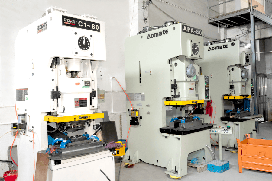
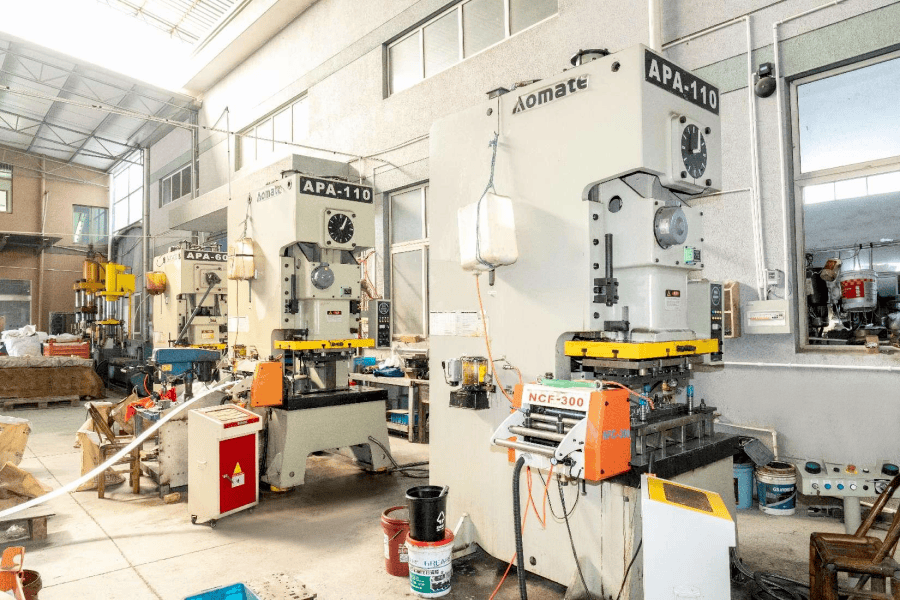
Our company profile at Ningbo Mingli Electric Technology reflects these characteristics. We operate a modern manufacturing base near Ningbo Port, about 25 kilometers from the shipping terminal, which supports rapid export delivery. Our in-house capabilities include high-precision stamping, sheet metal processing, internal thread processing, plastic processing, and welding, and we have served export customers across Europe, the Americas, Southeast Asia, and the Middle East. Our company overview describes our production philosophy and the range of industries we supply.
From Prototype to Production: Scaling Up Smoothly
A common mistake in product development is treating the prototype and production as separate projects with separate suppliers. When a sheet metal prototype is produced by one shop and production is transferred to another, the second shop has not shared in the design discussions, DFM analysis, or process development. This creates a repeatable pattern of surprises: the new shop rejects the design, renegotiates tolerances, or changes materials, and the schedule slips anyway.
Working with a single manufacturer from prototype through scale-up eliminates this risk. The same engineering team that reviewed your prototype geometry already understands the bend sequence, the weld fixtures, and the finishing requirements. When you move to production quantities, the process is transferred knowledge rather than a fresh start.
For high-volume production, stamping is the natural evolution from a fabricated prototype. Once the design has been validated and the annual volume justifies the die investment, a stamping tool produces blanks with far faster cycle times than laser cutting. Prototypes made with production-equivalent processes give you the confidence that the stamped version will meet the same functional requirements. If your design involves high-precision stamped components, our stamping metal parts page details the tolerances and capabilities we can bring to your production stage.
Cost modeling also changes at the transition point. A laser-cut and folded prototype might cost several times as much per piece as the eventual stamped part, but that gap narrows significantly once tooling amortization is included in the total project cost. A partner that can quote both the prototype and the production stamping tool upfront gives you a true picture of the program cost, rather than a misleading comparison of unit prices alone.
Practical Steps to Get Started
The decision to use rapid sheet metal prototyping is straightforward, but a well-managed project requires a structured approach. Start by reviewing your design for basic sheet metal rules: consistent material thickness, reasonable bend radii, adequate flange heights, and proper hole-to-bend spacing. Then export a neutral CAD format such as STEP or DXF, together with a drawing that shows material grade, thickness, and critical tolerances. Send this package to potential suppliers and ask for a quote with a confirmed lead time.
When the quotes arrive, compare more than the price. Look for suppliers that ask questions about the application, suggest process improvements, and offer a clear inspection plan. A supplier that takes the time to understand how the part will be used is more likely to deliver a prototype that validates your design correctly. The goal is not just to receive a metal part quickly; it is to receive parts that resolve design questions accurately, so that every day of the prototype schedule contributes to a better final product.
Plan for at least one second iteration. Even experienced engineering teams rarely achieve a perfect sheet metal design on the first prototype. Budgeting time and cost for one design revision is the realistic approach; a rapid prototyping partner that can turn around a revised version in a few days makes the second iteration affordable instead of painful.
Conclusion
Rapid sheet metal prototyping earns its place in the product development toolkit because it delivers representative metal parts fast enough to influence design decisions. It uses the same processes, materials, and tolerances that will define the production part, which means the validation data you collect is reliable. It eliminates hard tooling from the critical path, keeps iteration costs low, and, when paired with a manufacturing partner that can scale to production, it creates a seamless path from prototype to volume manufacturing. Engineers and procurement teams that adopt this approach get to market faster, with fewer late-stage surprises and a much stronger factual basis for the decision to approve tooling and mass production.
If your team is evaluating a metal enclosure, chassis, bracket, or assembly, the practical next step is to send the design to a qualified sheet metal manufacturer and request feedback on manufacturability, material selection, and lead time. The cost of a prototype is small compared to the cost of discovering a design flaw after production begins.
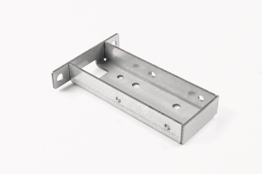
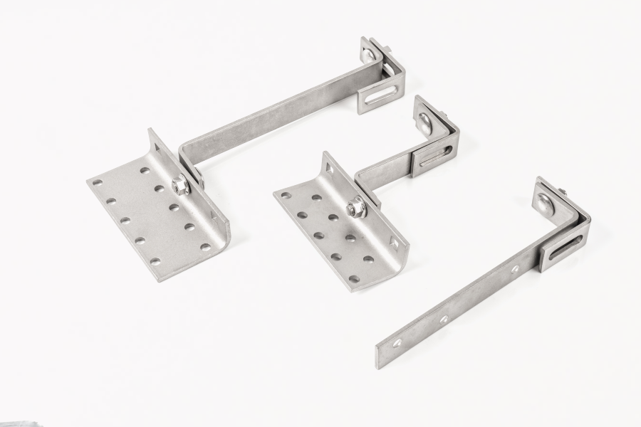

 Company Profile
 +86-189-57809418
 Zouxi Village, Tangxi Town, Yinzhou District, Ningbo City, Zhejiang Province, China
Copyright © Ningbo Mingli Electric Technology Co., Ltd. All rights reserved. Custom Hardware Parts Maunfacturers
